Regions and availability zones
Last updated on
STACKIT services run in regions, which are physically isolated locations. Each region includes three or more availability zones (AZs), typically three, and all AZs in a region are located in the same country. This ensures consistent compliance and low-latency communication within the region. The availability and functionality of STACKIT services are defined at the regional level. All AZs within a region provide the same set of capabilities. STACKIT ensures a bandwidth of at least 200 GBit/s and a latency of about 0,5 milliseconds between AZs in a single region.
STACKIT currently operates one region: EU01 (Heilbronn, Germany).
Availability zone architecture
Section titled “Availability zone architecture”Each availability zone (AZ) belongs to exactly one region and is logically tied to it. AZs operate independently, with separate power, cooling, and local network infrastructure.
An availability zone can take different physical forms:
- A standalone data center that meets isolation criteria
- A logical group of multiple data centers
- Multiple AZs hosted in a single data center with strict separation by fire compartments
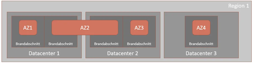
This diagram outlines how an availability zone may be physically implemented.
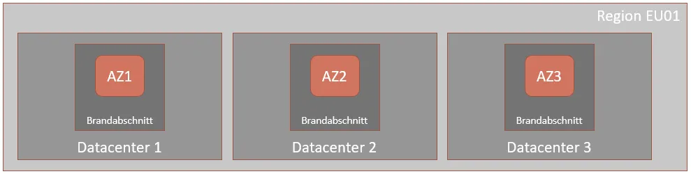
This diagram shows the architecture of the EU01 region as an example.
Service placement in availability zones
Section titled “Service placement in availability zones”When you deploy a STACKIT service, you an availability zone to it. You choose between two AZ scopes:
- Single AZ, which pins the service to a specific zone
- Metro AZ, which provides automatic failover across zones
Associated resources, such as disk volumes attached to a virtual machine, must reside in the same AZ.
Single availability zone
Section titled “Single availability zone”In a single AZ setup, a service runs in the specific AZ you select. It won’t be restarted in a different zone if an outage occurs. This setup is ideal for highly available applications that distribute components across multiple AZs themselves.
Distributing your services across three AZs can maintain uptime even during a zone-level failure. The services remain available as long as at least one AZ stays online, assuming your architecture supports automatic failover and load balancing.
Single AZs follow the naming format <region>-<n>, where n is the AZ number, such as 1, 2, or
3 (for example, EU01-2).
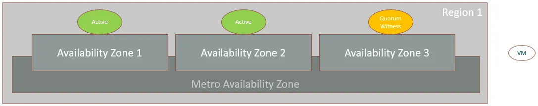
Metro availability zone
Section titled “Metro availability zone”Metro AZs span two or more availability zones within the same region. STACKIT automatically restarts services in another zone if a failure occurs. This improves resilience for workloads that don’t have built-in high availability.
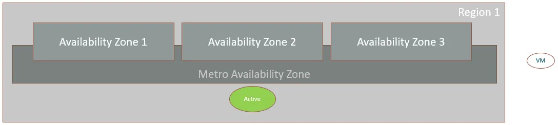
In this configuration, services run in one zone at a time but may be redistributed to another AZ if the original one becomes unavailable. This failover process can take time but significantly increases uptime for single-instance workloads.
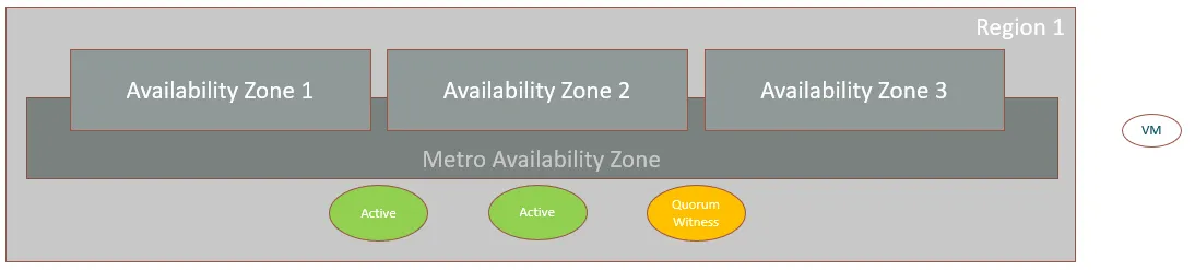
For high-availability workloads, Metro AZ behavior is less predictable. Because STACKIT places instances based on system load, all instances may end up in the same AZ. If that zone fails, the entire workload could be interrupted. For maximum control and uptime, consider using Single AZ deployments with service-level redundancy.
Metro AZs follow the naming format <region>-m, where m stands for “metro” (for example,
eu01-m).